On The Bench: Capacitors
When they ‘dry out’ some can do more damage than a bushfire. So why do capacitors fail, and which ones are the most susceptible?
Text: Rob Squire
Here on the workbench there’s one electronic component above all others that I deal with on a daily basis. Whether I’m refurbishing an old ’50s tube limiter, repairing console channel strips or hunting down an intermittent crackle in a microphone, capacitors are typically the star of the show, infamous for causing a broad range of faults in all sorts of audio equipment. Indeed, there’s probably no other component used that’s subject to more discussion, debate or diatribe than the capacitor, so this issue, let’s grab a handful and get our heads around what they are, and why they’re so demanding of attention.
CAP IN HAND
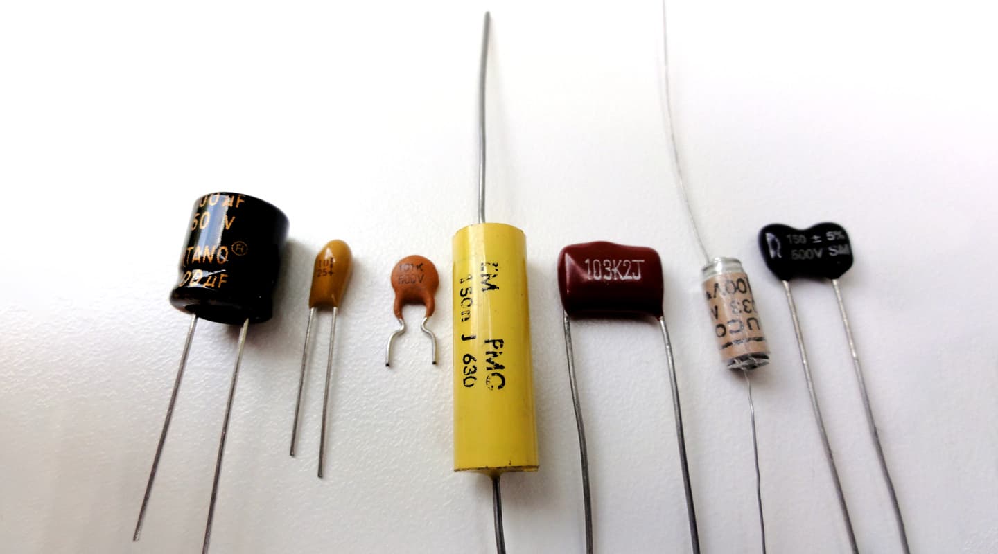
A capacitor – more commonly referred to as a ‘cap’ around the traps – is a device that stores electrical charge, consisting of a pair of conductors separated by an insulator. The ratio of this stored charge to the voltage between the conductors is a measure of the capacitance of the device. A set of hi-hats is another type of capacitor, albeit a very poor low-value capacitor providing very little capacity to store charge, where each cymbal is a conductor and the air between them an insulator. What’s required in a real capacitor is for the conductors to have a large sheet-like surface area, be very, very close to each other, helped along by an insulating material sandwiched between them. The insulating material, also called the ‘dielectric’ can consist of a number of materials: air, paper, various plastics, mica, ceramics and metal oxides, each of which has a quite distinct set of properties. The dielectric constant, or ‘K value’, of each material fundamentally affects the amount of capacitance available for a given spacing and surface area of the conducting sheets. The chosen material also determines the temperature stability of the device, its behaviour around water and heat, and ultimately the general name given to the capacitor type. Thus we refer to ceramic capacitors, mica capacitors, and polystyrene capacitors, and so on. Maximising the amount of capacitance in small caps usually involves either stacking alternating layers of conductor and insulating dielectric materials on one another in a multi-storey sandwich configuration or rolling up alternating sheets of conductor and dielectric, jam-and-sponge-roll fashion.
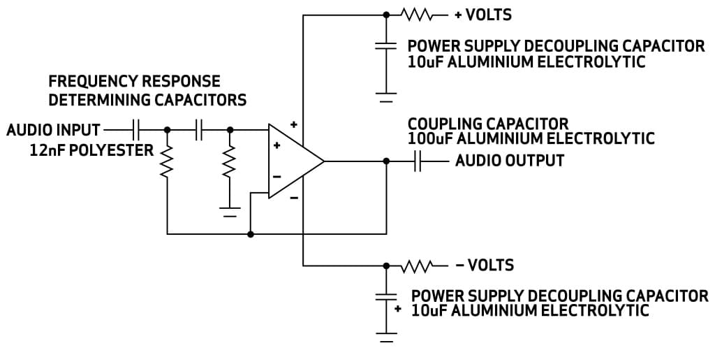
Caps exhibit rising impedance with decreasing frequency, in effect reducing current flow as the frequencies descend until ultimately at 0Hz – better known as DC – they have infinitely high impedance resulting in all DC current flow being blocked. In audio applications this fundamental property leads to caps being used for three fundamental circuit functions: blocking DC voltage from one circuit element’s output from the input of the next (a cap in this situation is called a coupling cap and is in-line with the signal path); power supply decoupling and storage, where the capacitor is placed across the power rails around circuit elements to ensure noise-free and stable operation; and frequency selective circuits such as filters and equalisers, where caps are exploited for their frequency-dependent characteristics.
THE ALUMINIUM ELECTROLYTIC
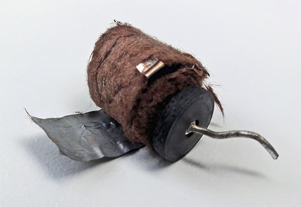
The most common capacitor type is the aluminium electrolytic capacitor. These caps are constructed from two conducting aluminium foils, one of which has an insulating oxide layer, with the foils separated by a spacer soaked in conductive liquid electrolyte. This is rolled up, placed in a cylindrical casing and fitted with two connection pins, or legs. This formula is cheap to manufacture and yields a cap with large amount of capacitance for its physical size. It’s polarised, meaning that any DC voltages applied across it must be orientated in accordance with the positive or negative markings on the body of the capacitor. The only other capacitor commonly available that cares about this DC orientation is the tantalum capacitor – other plastic and ceramic types aren’t concerned about their orientation with regard to DC voltages. Aluminium electrolytic and tantalum capacitors that have a reverse DC voltage applied to them will be destroyed by the experience (see pic, left), and if there’s enough power on hand at the time, often quite explosively.
The liquid electrolyte in this capacitor, while contributing to its cheap construction cost, ultimately leads to this type of capacitor’s downfall. Heat and time cause loss of the electrolyte: the cap ‘dries out’ – a familiar term to many – becoming less and less of a capacitor as time goes by. This leads to the daily grind of vintage audio repair and refurbishment: locating, testing and ultimately replacing dried out caps.
TO RECAP OR NOT RECAP
I’m often asked to speculate whether the caps in unsighted ‘Unit X’ need replacing. Sometimes I get the more direct request when a unit is sent in for service: “replace the caps while you’re at it can ya please Rob?”. I’ve poked a stick at hundreds of thousands of capacitors in my time, leading to some rules about capacitors and their replacement, but like all good rules, occasionally these get broken and at other times confounded by a new experience.
When an electrolytic ‘coupling cap’ in a signal path dries out two things happen to the audio passing through it: the overall level will be attenuated, and, in some instances, the low frequency response will be further depleted. These two symptoms of a degraded capacitor – loss of level and loss of low frequency response – are due to the cap developing a high resistance, and thus behaving more like a resistor, and the value of the capacitance decreasing. In any device that houses lots of caps in its signal path, such as a mixing console, this sort of degradation leads to strange variations in level and low frequency response from channel to channel, and output to output. From an operator’s point of view, a console in this state feels less precise and develops an aura of sonic uncertainty.
The thing that makes developing rules about replacing capacitors tricky is that different brands, and even different value caps within a single brand, degrade at vastly different rates. Even the physical position of a capacitor on a circuit board can affect its rate of degradation. Recently I was checking over caps on a very late model SSL 6000 console, and on one circuit card found three particular electrolytic caps of the same brand and value in each channel. In every case, across dozens of these channels, the same two capacitors tested fine while the third was badly degraded. The reason for this bizarre ‘consistent inconsistency’ only dawned on me after I positioned the channel strip vertically in its normal operating position. The degraded cap was located above half a dozen ICs that ran reasonably warm, whereas the two undegraded ones were located below these ICs. Simple convection (heat rising) had done its job on this one cap, the lower ones remaining just that much cooler and thus avoiding the most common killer of electrolytic caps – heat. This pattern was broadly spread across all the channel strips, where capacitors higher up on these large and deep circuit boards, had degraded more than those lower down.
TIME CAPS
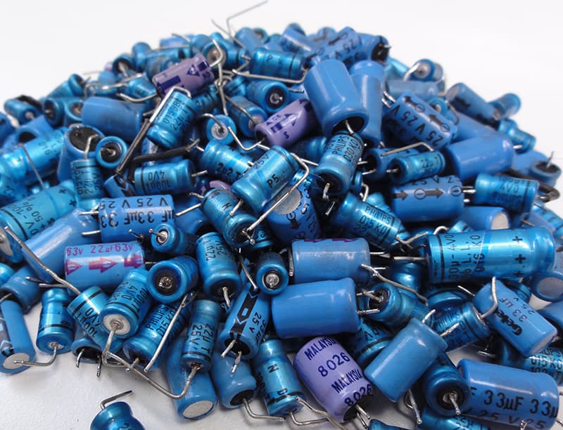
Time yields hard won experience, they say. Standing back and surveying the myriad brands and values of capacitors used over the years reveals how some brands and values within brands have stood up to the stresses of heat and time better than others. A prime example of this is the blue axial capacitor, manufactured by Philips from the ’70s to ’90s. This was a capacitor used by the truckload by UK and European manufacturers of pro audio gear. Found inside the Neve 51 and V-Series console, which run very hot, these capacitors have proven to be a cap that degrades very badly, sometimes fatally in these environments. There wouldn’t be one of these consoles left working on the planet that hasn’t had all its capacitors replaced by now. Indeed, those that made the mistake of replacing the capacitors with the same brand the first time around have now had to replace them all over again. Ouch!
For capacitors housed in these hot environments there are now, mercifully, electrolytic capacitors that have a higher temperature rating, meaning that their expected lifetime at a given temperature is increased. These 105º caps, as they’re called, are not much more expensive that the more common 85º caps, and generally speaking there are very few good reasons not to use them. I will always use 105º caps wherever possible in any device that runs at a temperature much above ambient.
Of course I can already hear yelling from the back row… “What about the sound? Some capacitors sound better than others and I’ve been recommended these special audio capacitors that are made on the forge of Zeus!” Well yes… and no, and maybe.
Like many of these audiophile perspectives, there’s a touch of science and a mountain of mysticism involved here. Different types of capacitors used in different types of circuits can have an appreciable influence. Here a designer schooled in the science will be able to choose the right capacitor for the right job.
Certainly capacitors such as polystyrene and polypropylene have very advantageous properties in circuits such as filters and equalisers or in high power circuits such as passive speaker crossovers. But since these types of caps don’t degrade with heat like aluminium electrolytics they aren’t the usual candidates for replacement. Also, their comparatively large physical size for the same given capacitance makes them physically unsuitable to fit into circuit boards where electrolytics were previously installed. Thus the argument often revolves around the best electrolytic brand type for the job. Enter the snake oil salesmen.
My rule is simple: if there’s heat around use a 105º-specified capacitor of an established brand you can afford. If choices need to be made, a low ESR [see the box item for an explanation of this term] capacitor is generally more versatile, meaning it is suitable as either a coupling cap or decoupling cap and may mean you only have to get one type instead of two. When replacing the thousands of capacitors in a large console the fewer types you have to deal with the better.
DSITORTION SPECS
Back in 2002 Cyril Bateman published a series of articles in Electronics and Wireless World magazine that was an exhaustive scientific study on distortion behaviour in capacitors. The series kicked off with the design and construction of a distortion analyser to conduct the tests, as nothing was readily available at the time that could probe the minuscule levels of distortion found inside capacitors. Ultimately he developed a system that could measure distortion down to 0.00003% and proceeded to conduct over 2000 distortion tests on various types, values and brands of capacitor. The broad conclusion of his work was that polypropylene capacitors were the best performers, and you’ll now see these type of capacitors used in high-end loudspeaker crossovers and where smaller value high voltage caps are required. For example, Avalon Designs uses these types of capacitors in the signal path wherever DC blocking is required.
For the more common aluminium electrolytic capacitor, distortion performance wasn’t as good but nothing measured much worse than 0.005%. This puts distortion factors well down into the noise floor of most equipment and is comparable with distortion factors of other circuit components. The one electrolytic capacitor that stood out as having generally better performance was the bipolar electrolytic capacitor. This capacitor is essentially two capacitors placed back-to-back inside one case. It doesn’t care about the DC polarisation like other electrolytics. When musing over replacement capacitors this type can be worth pursuing; the drawbacks being that they’re physically larger, more expensive and harder to source. Some manufacturers also see the value of the bipolar electrolytic. For example, the SSL 6000 console mentioned earlier uses several of them, whereas earlier versions of the console used the more standard polarised electrolytic.
TANTALISING TANTALUMS
Tantalums are also a commonly found capacitor in audio equipment. They became all the rage in the 1970s due largely to their physically small size for a given capacity and excellent very high frequency performance. Despite also being a polarised electrolytic capacitor they are most often manufactured with a solid electrolyte and thus don’t suffer from ‘drying out’ like aluminium electolytics, which extends their service life considerably. However, tantalums are very sensitive to the application of reverse polarity DC and current surges and when they die they don’t go gracefully, usually failing as a dead short. Worse, since they’re often used as decoupling capacitors placed across power rails this dead short invariably leads to other parts failing down the line, the chain reaction in some cases being quite catastrophic. History has shown that it’s rarely a good idea to use tantalums as a decoupling capacitor, especially with aluminium electrolytics now available exhibiting equivalent high frequency characteristics. The other quite common failure mode of tantalums is to become ‘crackly’, and frustratingly, often intermittently so. I had a U47FET in the workshop recently that would spit out a brief crackle once or twice every hour giving me uselessly narrow windows of opportunity to locate the faulty part. In the end simply replacing every tantalum capacitor in the microphone was the only expedient solution. Many condenser microphones use tantalums, taking advantage of their small size, and these parts are probably the most common source of faulty mics – whether that manifests as a ‘dead’ mic or an intermittent crackle.
Tantalums are certainly one capacitor that raises debate about the contribution of capacitors to audio quality or euphonics. Various studies – including Cyril Bateman’s – demonstrate that tantalum capacitors do have significant distortion qualities, and given their tendency to fail either to a short circuit or an annoying crackle, it’s always tempting to replace them. However, one place where you’ll find these capacitors used extensively is in Neve products from the ’70s and there is little doubt that replacing all the tantalums in a Neve 1073 does alter its sonic qualities. Given this, capacitor replacement – especially changing the capacitor type – should never be undertaken without reference to the role the capacitor plays in the circuit. As a rule I tend to replace tantalums used as decoupling capacitors with low ESR aluminium electolytics to avoid the grief of a dead short tantalum down the track, but always replace tantalums in coupling circuits with fresh tantalums.
For those of you heating up your soldering irons for a DIY project or to refurbish that big second-hand console you recently bought for a song, certainly give thought to the types and brands of capacitors used. Good brands of high temperature, low ESR aluminium electrolytics will be suitable in 90% of situations. Before you fork out the dosh, understand the role the capacitor plays in the circuit first and replace like with like, unless you understand the ramifications of any changes you make.








RESPONSES